
MacGregor Gyroscope Flight Controller
Detailed Settings Instructions
Product Specifications
| Working Voltage: | 4.5-6V |
|---|---|
| Response Frequency: | 100Hz |
| Working Temperature: | 0-50°C |
| Size: | 43 x 28 x 15mm |
| Weight: | 11g |
Caution In First Use
1. The voltage drop caused by the use of the servo may affect the stability of flight control. Please pay attention to ensure a stable working voltage.
2. For Delta wing/V-tail models, please turn off the internal mixing control of the remote control firstly.
3. If micro adjustments are made during flight, please perform power off and restart or neutral point calibration after landing.
Equipment Installation and Line Connection
Equipment Installation
1. Install and debug the fixed wing electronic equipment normally.
2. Place the long side of the flight control device parallel to the fuselage, the label surface upwards, and as close to the centre of gravity as possible and glue firmly at the centre line.

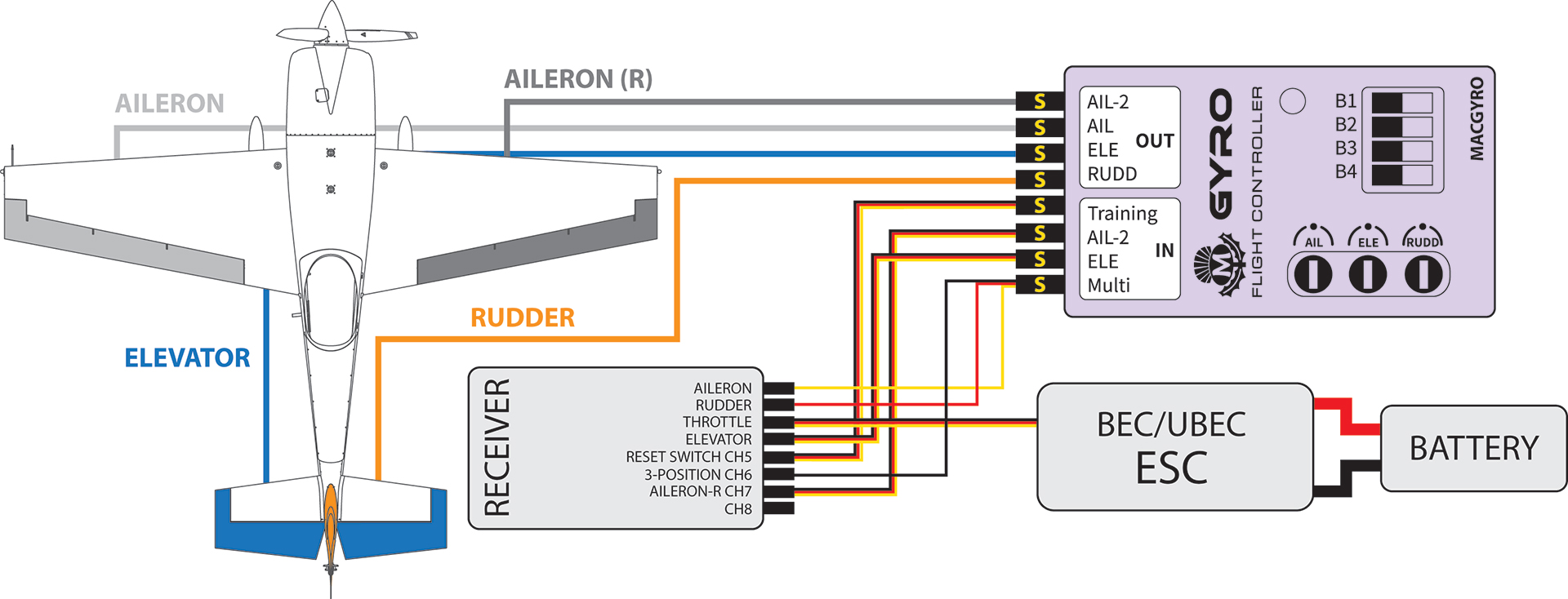
Line Connection (Please Note: Channel definitions vary for different receivers)
1. Aileron y-Y-line pattern
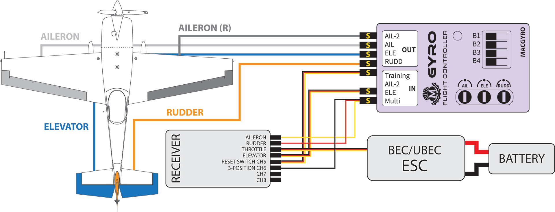
2. Left and right aileron are independently controlled (remote control required to set up double aileron channel, suitable for flap aileron mixing mode).
3. Power test: After about 5 seconds, the three rudder surfaces in the direction of aileron lifting will shake markedly, which means that flight control has been started.
⚠ - The first connection may require a power off restart
Mode Selection/Mode Description
Flight Mode Setting
Mode 1 - Aileron Balance Mode
This mode will keep the fuselage self-stable and limit the rolling speed of the aircraft; horizontal and vertical tail assisted stabilisation.
⚠ - This mode does not support the left and right aileron independent control.
⚠ - The maximum angle of the aileron in this mode is limited to ±75°


Mode 2 - Aileron Lock Mode
This mode will lock the attitude of the aircraft and limit the rolling speed of the aircraft. Horizontal and vertical tail assisted stabilisation.


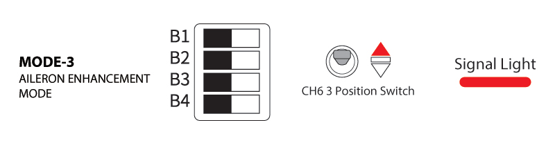
Mode 3 - Aileron Enhancement Mode
This mode will lock the attitude of the aircraft and limit the rolling speed of the aircraft slightly. Horizontal and vertical tail assisted stabilisation.

Mode 4 - Wind Resistant Mode
This mode will lock the aircraft attitude, horizontal tail and vertical tail to assist stability.


Mode 5 - One-Click Rescue Mode
In this mode, the fuselage attitude is adjusted to the level at a faster speed (quickly), and then the horizontal tail rudder is raised to pull the body up.


⚠ - This mode needs to keep the switch position, and the switch can be reset after the rescue is completed.
⚠ - This mode still requires throttle control.
⚠ - If the horizontal tail is not raised but lowered, the horizontal tail rudder can be reversed according to the following method.
Mode 5R - One-Click Rescue Mode - Horizontal Tail Reserve

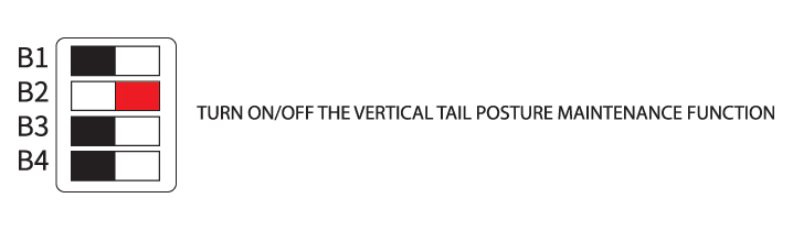
Mode 6 - The Vertical Tail Attitude Lock is On/Off
Turn Off Flight Control
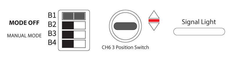
In any mode, put the 3-position switch in the middle position to turn off all functions of flight control (including one-click rescue function).
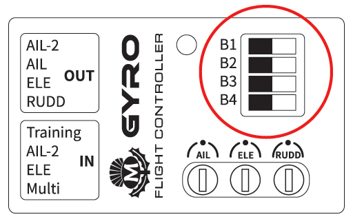
Sensitivity Setting
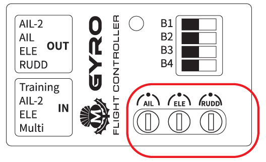
1. Sensitivity setting is an important part of flight control. When the knob is aligned to the 12 point direction, the corresponding channel of flight control does not participate in the work.
2. It is recommended to debug the sensitivity slowly from low to high, and the sensitivity is 0 at 12 o 'clock; The closer you get to 5 /7, the greater your sense of direction. Please note that excessive sensitivity can affect flight.
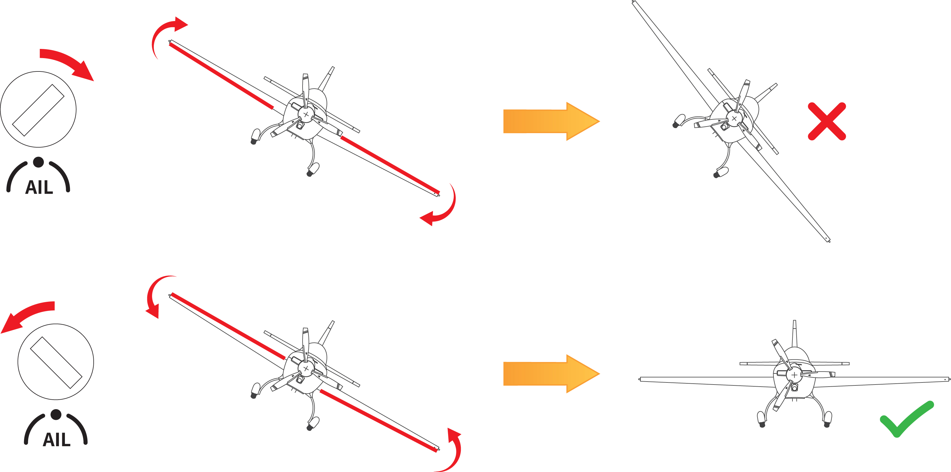
3. Take AIL aileron rudder surface as an example, flight control will start to work when the knob is rotated left/right. The greater the rotation angle, the higher the flight control sensitivity. When the sensitivity exceeds the threshold, the flight control overcorrects and causes fixed-wing jitter in flight. The threshold is different for different aircraft.
4. In the flight state, if it cannot be locked, the sensitivity is too low; if the aircraft jitters, the sensitivity is too high.

5. When the rudder surface is corrected in the opposite direction, please adjust the sensitivity to the other half turn.
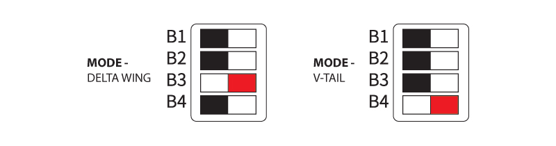
Select Model
Select the corresponding model, open B3 for delta wing model and B4 for V-tail model.
Save Neutral Point
If the steering gear (servo) will drift when switching modes, it can be solved by power o and self-test, or reset the neutral point.
When replacing the new adaptive model or remote control, most need to re-save the neutral point information, quickly switch the mode switch of the remote control three times, (CH6 three-position switch) will automatically save the current steering gear neutral point.
Other
1. When debugging flight control, please lock the throttle or remove the propeller.
2. Please confirm that the mechanical part is working normally. For example, the longer horizontal vertical connecting rod may affect the flight control rudder surface due to excessive resistance.
3. The faster the speed of the aircraft such as ducted fan aircraft, racing aircraft, etc., the lower the sensitivity required; The slower the speed of the aircraft such as training aircraft, gliders, etc. the higher the sensitivity required.